|
A stepper motor is a type of electric motor that is used when something has to be positioned very precisely or rotated by an exact angle.
In a stepper motor, an internal rotor containing permanent magnets is controlled by a set of stationary electromagnets that are switched electronically. Hence, it is a cross between a DC electric motor and a solenoid. Stepper motors do not use brushes and commutators.
Stepper motors have a fixed number of magnetic poles that determine the number of steps per revolution. Most common stepper motors have 200 full steps/revolution, meaning it takes 200 full steps to turn one revolution. Advanced stepper motor controllers can utilize pulse-width modulation to perform microsteps, achieving higher position resolution and smoother operation. Some microstepping controllers can increase the step resolution from 200 steps/rev to 50,000 microsteps/rev.
Stepper motors are rated by the torque they produce. A unique feature of steppers is their ability to provide position holding torque while not in motion. To achieve full rated torque, the coils in a stepper motor must reach their full rated current during each step. Stepper motor drivers must employ current regulating circuits to realize this. The voltage rating (if there is one) is almost meaningless.
Computer controlled stepper motors are one of the most versatile forms of positioning systems, particularly when digitally controlled as part of a servo system. Stepper motors are used in floppy disk drives, flatbed scanners, printers, plotters and many more devices. Note that hard drives no longer use stepper motors, instead utilising a voice coil and servo feedback for head positioning.
|
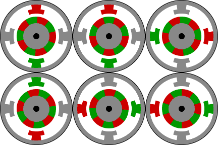
 FULL-STEP -
In full step operation, the motor steps through the normal step angle e.g. 200 step/revolution motors take 1.8 steps
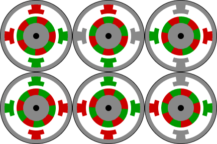
while in half step operation, 0.9 steps are taken.
